RSS

Blog #10 – INFR i3110 – CryEngine

Cryengine, one of the most famous game engine among game developers. Cry engine was developed by German company called “CryTek”. Cryengine is popular because of the free cryengine SDK. Many popular titles have been created using this engine like Crysis, Far Cry etc. The engine is compatible to work with PC, Xbox 360, Playstation 3, Playstation 4, Xbox One, Wii, Android and iOS.

CryENGINE3-Logo

Cryengine first started as a tech-demo for Nvidia, but when company saw its potential it turned into game engine. Far fry was the first AAA game to use this engine. The engine was redesigned and updated to version 1.3, with this update they have added HDR Lighting.

CryEngine 2 was released with the game Crysis. Cryengine 3 was released during 2009, when CryTek announced it at Game Development Conference. The new engine is developed to work with PC, Xbox 360, PlayStation 3 and WiiU. The PC version have added the support for DirectX 9, 10 and 11. On August 17, 2011 CryTek has announced the release of CryEngine SDK.

CyEngine SDK is the level editor, also known as Sandbox editor is used to create levels in cryengine. The tool also provide scripting, animation and object creation. The editor also features such as vehicles and physics, scripting, advanced lighting , Polybump technology, shaders, 3D audio, character Inverse Kinematics and animation blending, dynamic music, Real Time Soft Particle System and Integrated FX Editor, Deferred Lighting, Normal Maps & Parallax Occlusion Maps, and Advanced Modular AI System.

cryengine-3-sdk

I hope you enjoyed my blog! See ya’ later.

 
Leave a comment

Posted by on November 27, 2013 in Intermidiate Computer Graphics


Blog #9 – INFR i3110 – Frostbite Game Engine

Frostbite is among most powerful and visually appealing game engine in the current market. Many masterpieces like Battlefield and Need for Speed have been created using this. So let’s dive into this game engine and understand what frostbite is and how it stands among best game engine.

Frostbite is developed by EA Digital Illusions CE, Same Company who develops battlefield franchisees. Engine was first used as a simple first person shooter engine, but later it was expanded so other genre games can also be developed on it, for example racing and RTS games. But this engine is only exclusive to Electronics Arts and is not available for other developers. The current engine is designed to work with PC, PlayStation 3, PlayStation 4, Xbox 360 and Xbox One.

Frostbite 1.0 was released in 2008 with release of Battlefield: Bad Company. The engine featured HDR Audio as well as Destruction 1.0 which allows players to destroy objects. Frostbite 1.5 was released with Battlefield 1943 in 2009. I featured new version of destruction engine, version 2.0 which had even more features than before. Even though it had DirectX 11 shader support but windows games, it did not take full advantage full API.

Frostbite 2.0 released in 2011 with Battlefield 3. It took full advantage of DirectX11 and 64-bit processor while leaving DirectX9 behind. It also had improved version of destruction 3.0 adding more refined physics.

Frostbite 3.0 is current version of newly improved engine. It is going to be featured in Battlefield4, Need for Speed: Rivals and many other next gen games. It features improved version of tessellation and also featured new version of destruction engine.

I hope you enjoed by blog about Frobite engine. See ya`later.

 
Leave a comment

Posted by on November 20, 2013 in Intermidiate Computer Graphics


Blog #8 – INFR i3110 – Basic Artificial Intelligence (AI) in UDK – Part 3

Hello everyone, welcome to my eight blog.

In past two blogs, we have loaded a simple AI in our scene who will continue to run around the path nodes we have selected. Now let’s add shooting mechanic to him so every time he sees a player, he will start shooting.

So far we have this.

1

And your kismet editor should look something like this.

2

1) Now let’s open your kismet editor. We have noticed that kismet editor is really powerful tool of the UDK. Now we need an AI to enter into shooting mode when the player is in enemy’s visible spectrum. To do this. let’s create a new action in kismet editor called trace. To do this, right click > new action > misc > trace. And let’s connect Actor Factory “finished” node with “in” node of Trace.

3

2) We do not want AI to shoot when he does not trace player. So let’s put AI into loop where he keeps searching until he finds a player. So let’s add Delay. [Note: if you hold D key and left click in kismet editor, it will drop Delay action]. and change the time of delay to something like 0.5

And let’s connect Obstructed node of trace to In node of delay. And connect End node of delay to In node of Trace to find player again.

4

3) Now,lets suppose AI finds a player. And when he does that, we want him to shoot at them. Let’s right click> AI > Start Firing at. And Connect Not obstructed node from trace with In node of Start firing at.

Also, we have to specify who will shoot at whom. Let’s copy “enemy01” and “player 0” objects we have created earlier.

5

4) Now let’s connect Enemy01 object with “Start” node of trace and also “Target” node of Start firing at. And connect Player 0 object with “End” node of trace and also “Shoot at” node of start firing at.

6

5) Lets add another delay and, after that create new AI action called Stop Firing At. [ Right Click > New Action > AI > Stop Firing At]. Add another delay after it. And add another trace action after the last delay.And connects nodes like you see here.

7

6) We are almost finished with it. Now let’s connect Obstructed node of second trace to First delay we created.That means when player enters outside AI’s visible spectrum, he will stop firing.

8

And Connect Not Obstructed node of second trace with Start Firing at In node. So AI will keep shooting until player is out of his visible spectrum again.

7) Now when we try to play this level, you will see AI firing at you. But when you kill him, UDK will throe warning on left bottom side of your screen. It is because UDK does not know what to do with “enemy” variable when AI is destructed.

8) So let’s go back to Kismet Editor. Let’s right click > new action > event and select “attach to event”. And connect Actor factor’s finished with In node of attach to event.

9

9) Now we have to attach death of AI event with “attach to event” action. Right click > New Event > Pawn > Death. And connect Event node of attach to event action with Death event. [Note: you have to drag an arrow onto Title bar of the Death event]

10

Also connect “enemy01” variable [displayed with ??? inside it] with attachee node of “attach to event” action.

11

Now we have to clear out enemy variable. So right click > new action > set variable > object. Connect Out node of death with In node of Object. And also connect enemy variable with Target node of Object.

12

Now, we are done. Let’s play the level, and you will see enemy shooting at you. And when you kill an AI, no warning will be thrown.

So with these three blogs, we know how to create an enemy in UDK, and we can apply similar technique in any other game engine.

I hope you enjoyed it. See ya’ later.


Leave a comment

Posted by on November 13, 2013 in Intermidiate Computer Graphics


Blog #7 – INFR i3110 – Basic Artificial Intelligence (AI) in UDK – Part 2

Hello everyone, welcome to my seventh blog.

In this blog we will make an AI movement from one path to other. If you haven’t checked my last blog than you should, it covers how to load an enemy AI in the scene.

one

so this is what we have so far. Let’s get started.

1) Let’s go to our kismet editor. Now we want our enemy to follow path nodes that we have placed before. Path node is one kind of Actor. So we right click in kismet editor and select New Action > AI > Move to Actor. This will drop a small box which has one input and three output.

2

2) Let’s connect Finished node of Actor Factory to In node of Move to Actor.

3) In last blog we have created a variable to hold every data of our AI. Now we want to access this variable and connect it to Target node of Move to Actor. To do this right click in editor and select New Variable >  named Variable. This will drop a circle with cross mark in it. Now we have to tell UDK which variable is it connected to. So got to properties by selecting named variable circle. And inside Find Var name field enter the name of the variable that you gave to your enemy. In my case that is “Enemy01”. After this connect Named Variable to Target node of Move to Actor.

3

4) Now we have to add all path nodes where the AI will move. So minimize editor and select all path nodes from the scene and come back to editor. Now right click on Destination node of Move to Actor action. And select “New object vars using…”. This will drop all path nodes in editor and all of them will be connected. You can hold Ctrl and left click drag to move nodes on desired place.

4

5) Now we want a delay between movement when AI moves from one path node to another. This can be simply done by selecting delay from “New Action > Misc > Delay”. By default delay is set to 1 sec. lets leave it for now. But you can change the value of delay by changing value in its property. Lets connect finished node of Move to Actor to Start node of Delay.

5

6) We also have to add Player to Look At node of Move to Actor. We can hold “P” and left click in editor to bring a node in. It will say “All Player”. to concentrate AI on just our player we go to Player properties and Under Seq Var Player you will see an option called All Player. Uncheck that option, now AI will just look for our character. Connect Player node to Look at node of move to actor.

6

7

7) Now to complete the movement we add Move to Actor action again and connect Enemy node with Target, All path nodes with destination and Player to Look at node. Also connect Finished node from delay to In node of second move to actor action.

8

8) Lets add another delay action. and connect our second move to actor’s finished node to in node of our second delay. And also connect finished node from second delay action to In node of first Move to Actor action.

9

9) Lets build our game and play it. You will see an enemy will run from one path to other while looking at our player all time. Let’s add shooting mechanic to our enemy in next blog.

Here is the simple video i made.

I hope you enjoyed it. See ya’ later.

 
Leave a comment

Posted by on November 5, 2013 in Intermidiate Computer Graphics


Blog #6 – INFR i3110 – Basic Artificial Intelligence (AI) in UDK

Hello, welcome to my sixth blog where I will show you basic AI in UDK.

In this blog I will show you how to create path node, spawn enemy and basic pathfinder for enemy as well as working with UDK’s Kismet editor. Since this is a large topic to cover, I will split this tutorial in two blog. In this specific blog we will spawn an enemy using Kismet.

So let’s start.

1) Create a simple plane and a wall and texture it if you like. My previous blog has a brief explanation of how to create a good small level in UDK. You can even use a default world that UDK provide.

2) Now let’s go to UDK’s kismet editor, by clicking on a green K icon beside content browser.

3) Kismet editor will open. This is where you can create a sequence or a logic that will appear in a game or a demo. But before we jump into Kismet editor let’s minimize it for a second and add a path node in our scene.

Path Nodes are essential’s for AI movement in UDK. Let’s create about 5 path node surrounding a box. You can create a path by right clicking on a place where you want path node in a scene. Now click on Add Actor > Add PathNode. A path node will be created on this place, a path node looks like an apple. Let’s repeat this process 5 times and place them around a box. It will be look something like this.

4) Now let’s go back to Kismet editor. This is where we will create a sequence or a logic for an enemy so he will randomly run from one path to other.

We want an enemy spawned when the level is loaded. To do this we have to create a “Level Loaded” event. This means an event will be called when a level is loaded. To do this right click on large grey area in kismet editor and click on New Event > Level Loaded.

[Note: You can hold Ctrl + left click drag to move this entity in kismet editor]

5) Now we need an actor factory which will manage our enemy. To create an actor factory, right click New Action > Actor > Actor Factory. This will create a box with many entities in it. Most of them are self-explanatory. Now we need to spawn an enemy when the level is loaded. So let’s drag a mouse “Loaded and visible” from Level Loaded to “Spawn Actor” in Actor Factory.

6) We have to choose what to spawn with actor factory class now. Click on Actor Factory box and it will highlight yellow. When this happen look at properties window in kismet editor. This is where you can change properties for selected entities.

We want to create an AI factory. Select a blue down arrow in a “Factory” property under “Seq Act Actor Factory”. (Make sure Actor Factory is selected)

A large list will open. Choose ActorFactoryAI.

For Controller Class select “UTBot” and for a Pawn Class select “UTPawn”. So UDK will load Bots from Unreal tournament which are already designed. You can even give your enemy an Inventory. Let’s give him a rocket launcher. To do this, click on green plus icon for Inventory List and choose Rocket launcher.

7) We have an enemy, but we didn’t specify where to spawn enemy. So let’s minimize kismet editor and select any path node from the scene. Only select one path node. Now come back to kismet editor. Now when you right click in kismet you will see something like “New Object Var Using PathNode_0” [Path node name might be different in yours]. Let’s select this option and drag an arrow from Spawn point from actor factory to this object.

8) But now we need a variable to hold our enemy data. Just like C++ would do. To do this, Right click > New Variable > Object > Object. This will create a circle with “???” inside. Let’s drag an arrow from Spawned from actor factory to this variable. But just like C++ we will have to name this variable. To do this select a newly created variable, in properties window you will see “Var Name” under Sequence Variable. Select where the “none” is written and change it to any variable you like. For this tutorial I am going to type “Enemy01”. It will looks something like this.

9) We have successfully created an Enemy spawner. But there is one little thing missing before we can see an enemy in game. Since we are using “UTBot” actor from UDK game, we must set our game type to “utgame”. To do this, go to View > World Properties. And you will see “Game Type” category. Expand it and choose “utgame” for Default Game Type and Game Type for PIE. Close the window and Build All and Play.

You will see an enemy with rocket launcher spawned if everything works perfect. He will not move or attack you. We will do this next blog.

This is all for this week. See you next week.

 
Leave a comment

Posted by on October 28, 2013 in Game Engine


Blog #5 – INFR i3110 – Understanding Nodes and Entity in Ogre

Hi, in this blog i will give a brief explanation of nodes and entity in ogre scene graph and how the transformation works between nodes.

The Nodes are ogre way to render scenes in an organized way. Nodes are connected to their parent nodes and can have as many children as well. In the end all these nodes should be connected one way or the other with the root scene node. Render-able objects in ogre are called Entity. They should be connected with nodes. each node has a transformation value that carries over to their children. So all the position, scale and rotation values are carried to its child nodes.

The following diagram shows the perfect representation of nodes in Ogre.

1


Here you can see that Root Scene Node is a main node for ogre in scene graph. All entities and other nodes must be connected with it.

Node 1 is connected with the root scene node. That means RootSceneNode is the parent of the Node 1 or in other word, Node 1 is the child of RootSceneNode. This can be represented in a code as followed.

manager->getRootSceneNode()->addChile(Node 1);

Node 1 also has a position which is 10 unit in Y direction and 1 unit in Z direction. So all entities and child nodes connected will also have this transformation applied to it.

Node 1 does not have any entities connected to it but it has two child nodes, Node 2 and Node 3. Node 2 has a position of (0,0,10) and Node 3 has a position has position of  (10, 0, 10). And both of these nodes have a entity connected to it most probably a mesh. But since Node 2 and 3 are child node of Node 1, Node 2’s final position will be at (0, 10, 11) and Node 3 final position will be at  (10, 10, 11). This is because these two nodes were already at a (0, 10, 1) when Node 1, their parent transformed. So Entity 1 and Entity 2 will be displayed on (0,10,11) and (10,10,11) respectively.

This is just a basic understanding of the node hierarchy in Ogre. In a real life example we can understand a house to understand node hierarchy. So a House is a Root Node, and It has several nodes like bedroom, living room, kitchen and they have their own child like drawer, sink and computer table and so on. So when a house moves every nodes of it moves with it, but when a computer table from bedroom moves, only a table and its child moves with it.

I hope you enjoy this blog and find it informative. See ya’ next time.

 
Leave a comment

Posted by on October 21, 2013 in Intermidiate Computer Graphics


Blog #4 – INFR i3110 – Texturing & Static Mesh in UDK

Texturing in UDK is rather simple but robust. If you are importing geometry directly from content browser than the mesh should have appropriate material attached to it. But if you create your map out of BSP brush than you can attach materials to it.

So, let’s get started.

In last blog we have made a simple room in UDK.

We have this from last blog. If you do not have some kind of level in UDK, than make it or just follow this blog.

1

Now let’s open a content browser by click this icon from top icon bar.

2

Let’s use some material that already comes with UDK package. Select UDKGame from left panel under Packages in content browser, left click on it and select Fully Load. This will load all data that comes with UDK from the beginning. Now select UDKGame and check “Materials” box under Object type from right side of content browser. Let’s search for a ‘floor’ material.

3

Select any material you like, I am going to select M_LT_Floors_BSP_Dark_TileBreak_02. When you select it, that material will have yellow border.

4

Now minimize Content Browser, and make sure you have selected you material. Now let’s select a floor and right click on it. And it should a option called “Apply Material: (Your Material Name)” Select it. Your should see your floor will have a material applied to it.

5

Now let’s say you want same texture to be on the floor inside your room too. Well, you can always do right click > Apply Material to it. But if you have to apply same material on many faces it becomes boring work. But in UDK there is a shortcut to copy texture and keep applying in the faces. Now Lets hold Alt and Right click on the floor which already has a material on it and hold Alt and left click on the faces you want to apply material on. After you are finished, you should see something like this.

6

I will apply different materials on rest of the faces. And you should have something like this.

7

Now materials on wall doesn’t look right. Well we can always change U and V of the texture on the surface. Let’s double click on one of the wall surface.

8

This is a texture editor where you can select how it is projected on the surface. For now we just want wall texture to be big so the texture doesnt look repeated. You can change the value of U and V to match you need. But first let’s select all outside walls by holding Ctrl and left click. And try different value of U and V.

For my material, U and V at 0.33 seems fine. You can also pan the material in U or V direction to match it perfectly. I’ve panned few times in V to get the following result.

9

Now close the texture editor window and do the same for other materials and you should end up like this.

10

Now lets go to content browser and instead of material select Static Mesh. and search for object.For example I searched for barrel and got two result for barrel under static mesh.

11

Just drag and drop any meshes you wish to add in you level. These are the snapshot of my finished level without lights.

12 13 14

Here are more snapshot with lights in the scene.

15 16 17 18

I hope you like this tutorial. See ya’ later.

 
Leave a comment

Posted by on October 13, 2013 in Intermidiate Computer Graphics


Blog #3 – INFR i3110 – Getting Started and BSP brushes in UDK

In this blog post, I will guide you through basics of staring in Unreal Development Kit and also introducing BSP brushes inside UDK to build robust level.

So,first thing we will have to do is download and install Unreal Development Kit.

1.) Go to http://www.unrealengine.com/udk/ and click on Download button. And download the latest UDK beta available.

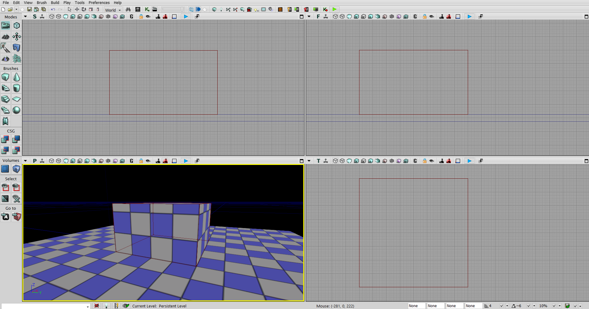
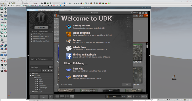
2.) Install the UDK on your system, and open the “UDK Editor” application. You will see something like this.

1

3.) Close all the pop-ups and click on File > New Level. and click on “Blank Map”. If you do not see a red lined box in the middle, press “B” on your keyboard (This is shortcut to toggle between brush visibility)

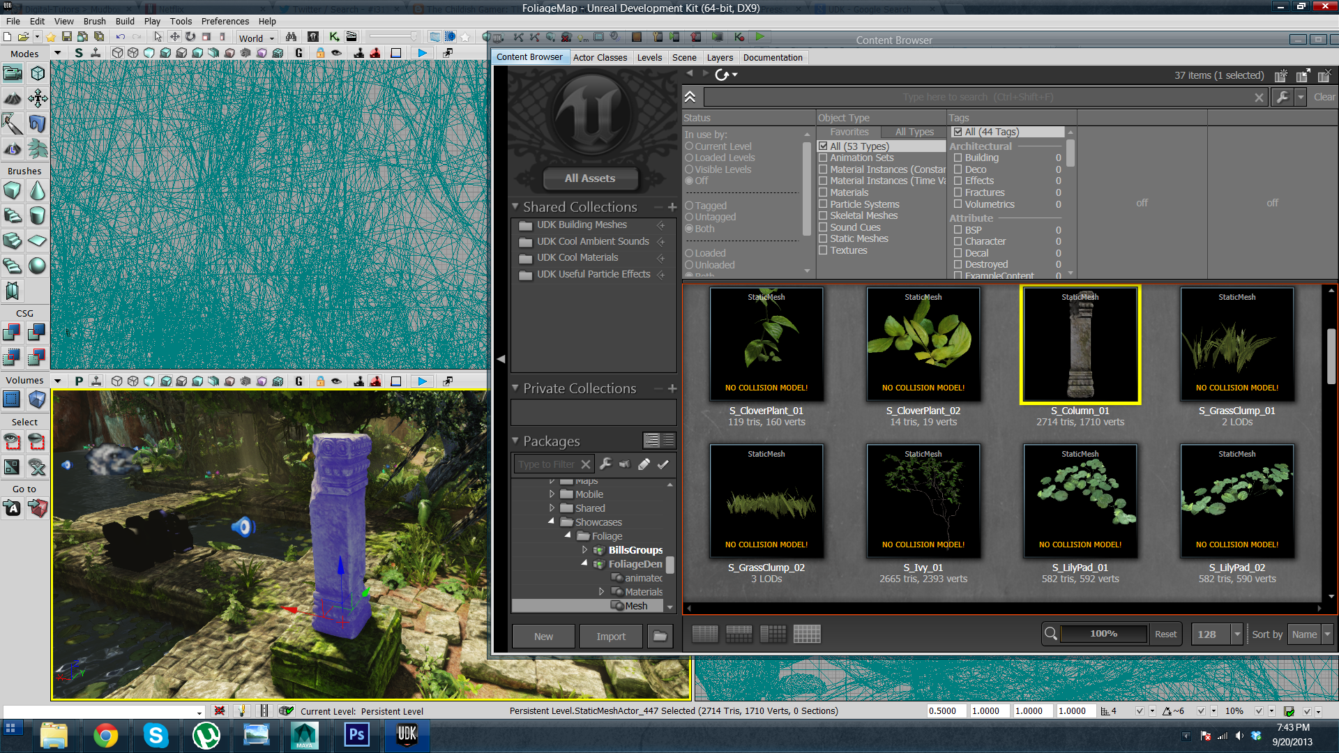
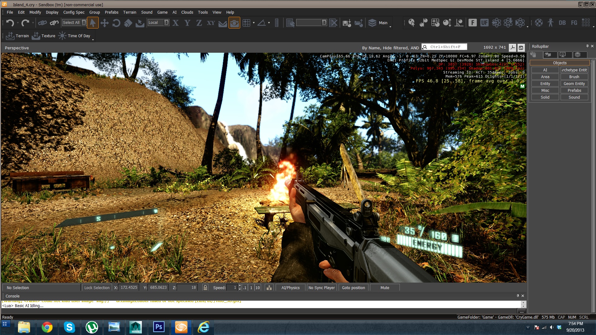
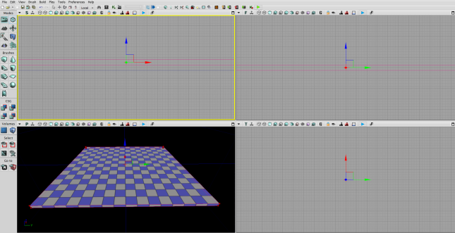
4.) UDK is a game engine with GUI integrated. Even though it might not have many options like Unity or Cry Engine on the screen, it is managed to push so many features in the package.

5.) UDK has a simple interface and a navigation. “WASD” keys to move inside UDK viewport. Hold right mouse button and move mouse to rotate camera. Hold left mouse button and drag mouse to move camera in world axis.

6.) Now first thing to get started with UDK is to learn about BSP brushes. Now the reg lined box in the middle of the viewport is a BSP brush outline. You can select it, move it, rotate it and also scale it.

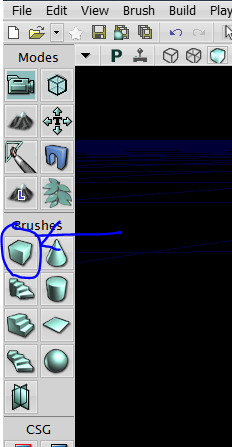
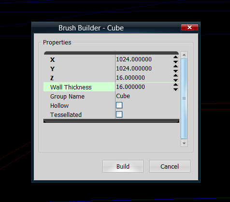
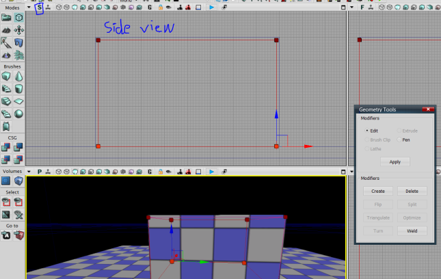
7.) Now we will go through a process to create a simple room with BSP inside UDK. We already have BSP inside our viewport, but how do we change its size? To do this right click on the button shown below.

2

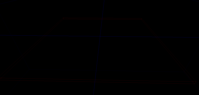
8.) A small window will pop up. This is where you define the size of the brush. I want to create a plane first, so I will enter X= 1024, Y=1024 and Z=16 to create a flat plane. We won’t have to worry about the other option. Now click build. and hit cancel.

3

9.) This action does not build anything but it will just change the size of the BSP brush. You will see something like this.

4

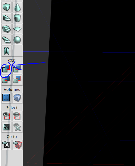
10.) Now we want to build a geometry from where the brush is placed. to do this hit “CSG Add” button from the left panel or simple hit Ctrl + A.

5

11.) Now using the same technique we will create a small room on this plane. So select the BSP brush and move it a little bit up so the bottom of the brush is on the top part of the plane. If you want to match perfectly then hit “Alt + X” to go open four viewport and adjust it in front or side view.

6

12.) Now change the brush size by right clicking on cube button is left panel, and move the brush where you want to put a room. and hit “Ctrl + A

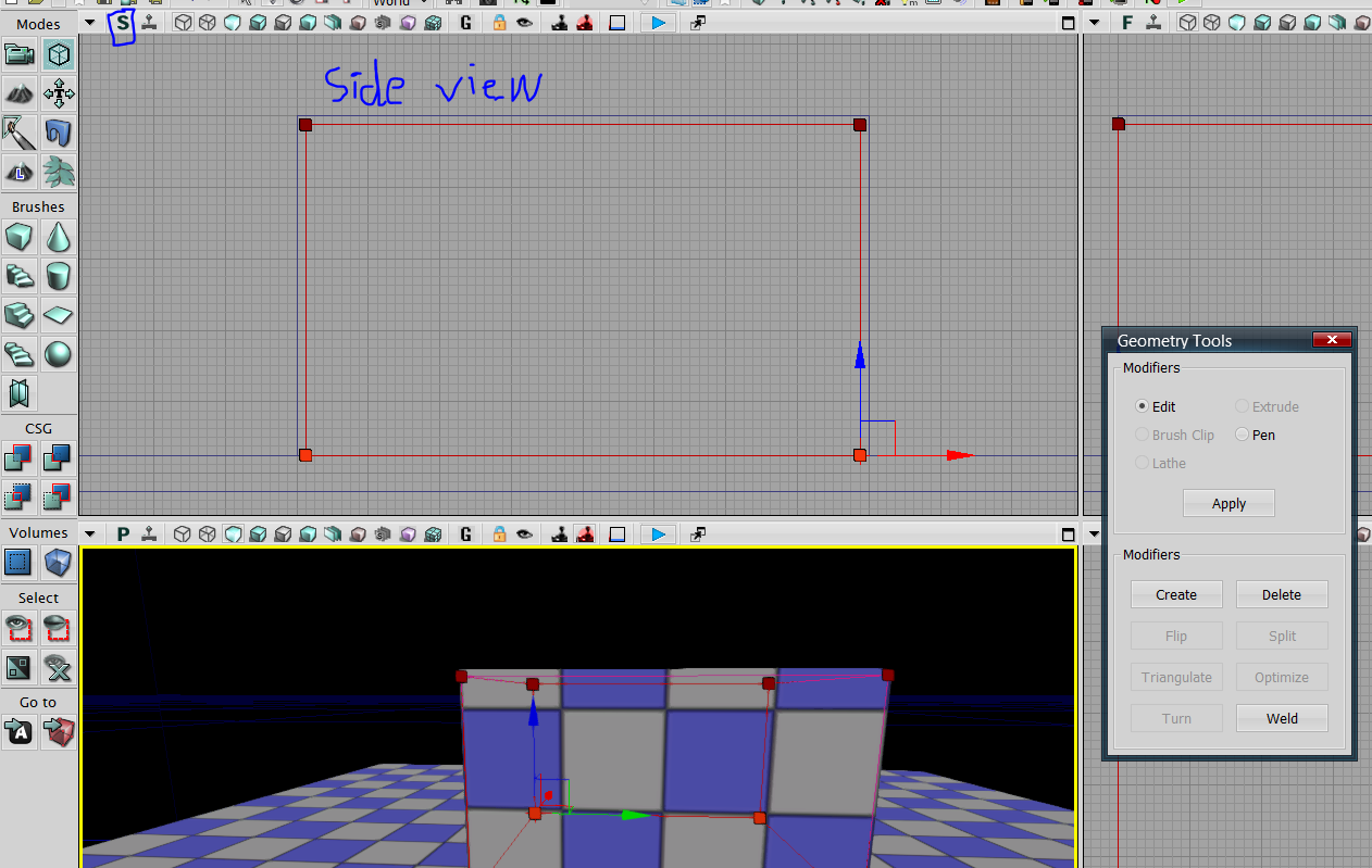
13.) Now let’s say you want to move geometry by moving the vertex like you can do in maya. To do this click on Geometry Mode from left panel or hit “Shift + 2“. This will open a popup. Let’s not pay attention to popup yet. But this mode will allow you to change geometry of the BSP brush.

7

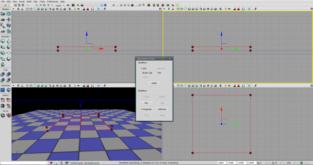
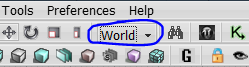
14.) If you look at the image above, I still haven’t adjusted a height of the room. To move vertex of the brush you can simply click them and move it. If you want to select multiple vertex by dragging, hold “Ctrl + Alt” and while holding drag mouse around vertices to select them and move them up to create a proper height for a room. make sure you are working on the “World” axis when moving. After moving hit “Ctrl + A” to build a geometry. [to exit out of geometry mode simple close the popup box called “geometry tool”]

8

9

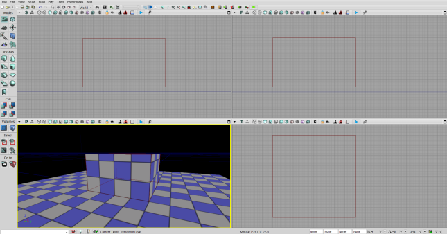
15.) We only have created the outside of the room. Now let’s create an inside of the room. Let’s click on our brush and hit “Shift +2” and go to geometry mode.

16.) To create a hollow room, we must come go to every view [hit Alt + X to open 4 viewport] and move all vertices of the brush slightly inside.

10

11

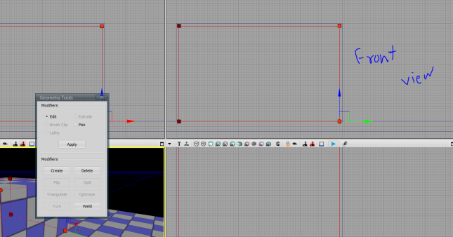
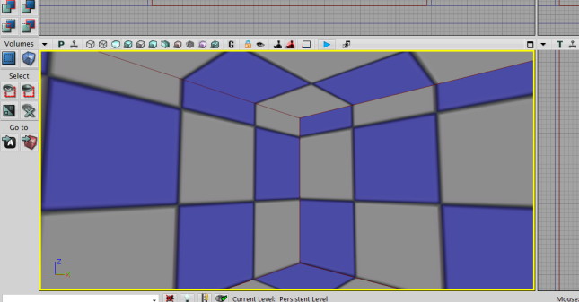
17.) Now the brush is actually contained inside other box. So we cant add geometry there, because virtually the geometry exist there. So to create a wall inside we have to subtract the geometry from the box we have created earlier. To do this click on “CSG Subtract” from left panel or simply hit “Ctrl + S” and this will subtract geometry. To view this move your camera inside the box and you will see a wall inside.

12

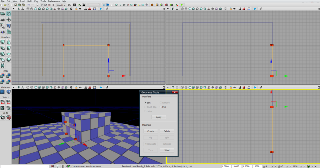
18.) Now lets move to the final step and create a door way. Here we will look at the different technique to subtract geometry. If you go to you Front, Side or Top view you must see other geometry we have created earlier are displayed in blue and dark yellow [if you don’t see dark yellow hit “B” key to hide your brush]. These are not just random color, but they mean something. The blue line means this geometry was added while dark yellow means it was subtracted. Now we now that geometry for the door is gonna subtracted from the actual room. So we can just use the dark yellow brush that we have created before. Now select the dark yellow bush in the view port [only visible in front,side and top view] and press “Ctrl + D” to duplicate the object. Now go to geometry mode and re-size the brush to match the door

13

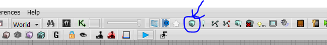
19.) Now this brush is subtraction brush already, so hitting Ctrl + S will not do anything. So to build this geometry simple click on “Build Geometry from Visible Levels” from the top bar.

14

20.) It will open a pop-up and throw few warning and errors, ignore it and hit Close. And you will see door is already created.

15

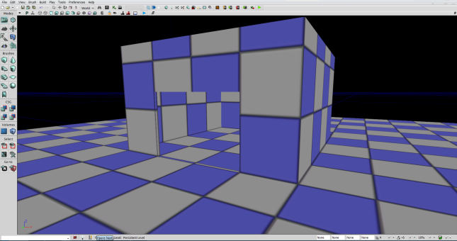
In next blog we will work on adding materials, and also adding 3D models those are created in the scene.

See Ya’ later.

 
Leave a comment

Posted by on October 6, 2013 in Game Engine


Blog #2 – INFR i3110 – Working with Havok in Maya

In this blog, I will guide you through getting havok for maya, installing and creating sample scene in maya with Havok physics applied and finally preview it.

So first, let’s get Havok for Maya. Go to http://havok.com/try-havok and fill out the form and click submit.

And then download “Content Tools for game Artist & Designers” for your appropriate autodesk product.

After downloading simply install the application file. When it asks for which software to install havok for, make sure you choose Autodesk Maya.

Now, Installing the havok is done. Let’s create a simple havok scene in maya.

1.) Open Maya. And go to Window > Setting/Preferences > Plug-in Manager

1

2.) And check the plugin for havok in maya as shown below.1

3.) Now Let’s create a plane on the grid at (0,0,0) and create a box on top of it. Rotate the plane a little bit so the box can slide of it easily.

1

4.) Now we apply Havok rigid body node to these objects, To do this select a plane and go to Havok Content Tools > Physics > Create Rigid Bodis. Now select a cube and follow the same procedure but in the attribute editor enter the value for mass (eg. 10). We do not need to enter mass for plane, because leaving mass to 0 means the object won’t move.

5.) Now go to Havok Content Tools > Export.

1

6.) Now go to Physics tab on left side and select Create Rigid Bodies and click on “Add >” button. Than select Create World and click add. Than finally go to Graphics tab and add preview tool.

1

7.) Click on “Run Configuration” and new window will open where you will see a box falling on the plane and sliding from it.

1

Creating rigid body objects in maya is easy, I am still trying to figure out skeletal meshes in havok.

See ya’ later.

 
Leave a comment

Posted by on September 29, 2013 in Game Engine


Blog #1 – INFR i3110 – My Experience With Game Engine

Around five years ago I had no idea how these 3D games were created, all I knew was you create 3d model somehow and apply little magic to it and there you have it. I had no idea about the complexity behind games. I just enjoyed playing them, never tried to study it. So one day I opened a web browser and googled “How to create a game”, literally. I opened a first link where one guy asked same question on yahoo. So, I went back and click on the second link and landed on Unity website. And I caught the word Game Engine from it. I downloaded and installed free version of Unity and opened a pre-made project where I spawned in a jungle. I tried to work with its GUI but I felt it extreme and closed it and never looked at it again.

After few month I was browsing through youtube videos and suddenly my caught onto one video from suggestion bar. It was about Unreal Game Engine Tutorial. I knew I have heard game engine before so I downloaded UDK and started following the tutorial step by step. I learned to work with brush and apply material to it. It was cool to play on a little test world I have created. And then due to my high school study I forgot about UDK too. Until now…

Untitled

Last Year I have started learning about game engines again. And I’ve also found about the juggernaut in game engine industry which really caught my eye, “The CryEngine”. I have played Crysis I & II and I have really liked their graphics. But I found out about cryengine through the game called FarCry 3. I looked at few demos created on cryengine by various people. I also checked out their website for the features they have included and it really caught my eye.

Untitled

So I started learning all three engines (Unity, UDK and CryEngine) in the summer. Learned the basic of unity, started messing around with UDK material and content browser, created terrain in cryengine, worked basic with kismet system in UDK, painted texture in unity and messed around with lighting in cryengine. It was a fun ride and I would like to share my basic knowledge of game engine with you in my next blog post.

Here is my quick opinion about these three different engine.

– Unity, is great for game prototype, but it just can not hold larger games. It is by far easiest engine to use among these three. There are few games out there which uses Unity but there graphics are no where near to most AAA games graphics.

– UDK, Most popular and oldest among three. One of the most matured game engine in the business. Hard to use but it can get your work done. Many AAA games were built on this engine. Their latest major SDK which is Unreal Engine 3 was released almost 4 years ago and it is still being used in many new and next-gen games. Best documentation and community in my opinion. One of the best but arguably not best.

– CryEngine, the engine that has it all. It has almost everything that is being used in most AAA games. Best choice among three. Little bit harder to get custom 3d models inside but it is not a rocket science.

See ya’ until next time.

 
Leave a comment

Posted by on September 20, 2013 in Game Engine